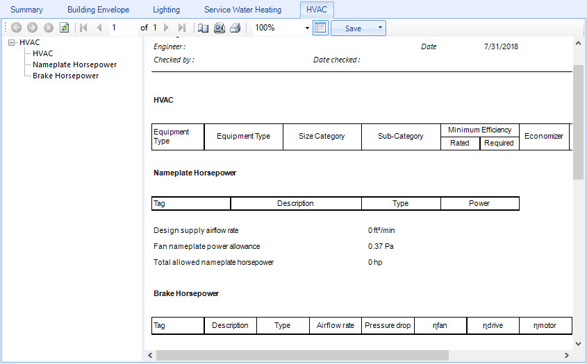
| HVAC
|
Displays prescriptive results for the HVAC systems
in the project building. The results reported here provide information about
each piece of HVAC equipment which is then used to determine if the HVAC
systems comply with the minimum power efficiencies required by the standard.
- Equipment Name –
Lists the name of each piece of HVAC equipment in the building.
- Equipment Type –
Lists the type of equipment each piece of HVAC equipment is. Equipment types
displayed here include air conditioners, condensing units, and heat pumps.
- Size Category –
Lists the size categories which determine the compliance eligibility of each
piece of HVAC equipment in the building. The categories are taken from the
minimum efficiency requirements for listed equipment tables that are provided
in the standard.
- Sub-Category –
Lists the equipment sub-category or Rating Condition. Rating conditions are
used to adjust minimum efficiency requirements because simulations can not
completely simulate every aspect of HVAC systems.
- Minimum Efficiency
– Lists prescriptive results for the factors that determine the minimum
efficiencies required for each piece of HVAC equipment in the building. To
comply, the HVAC equipment must meet the minimum efficiency requirements for
listed HVAC equipment which is determined at specific rating conditions and
tested in accordance with specified testing procedures.
- Rated – Lists
the rated efficiencies (determined by prescribed tests by the manufacturer) for
each piece of HVAC equipment in the building.
- Required –
Lists the required minimum efficiencies for each piece of HVAC equipment in the
building calculated using the equipment information such as type, size category
and sub-category.
- Economizer –
Displays
Yes when an economizer (outside air
controller) is present in an HVAC system. Economizers are useful when some
cooling is required even when the outside temperature is lower than the inside
temperature. An economizer is a damper opening that draws up to 100% outside
air when the outside air is cooler than the temperature inside the building,
providing free cooling.
- Pass/Fail –
Displays an overall result of the HVAC equipment compliance with the HVAC
requirements prescribed by the standard.
|
| Nameplate Horsepower
|
Displays prescriptive results for the fans in the project
building when the nameplate compliance option is used (Section 6.5.3.1 Fan
System Power Limitation). The results reported here provide information about
each fan which is then used to determine the fan power limitation for the
building. Fans are typically the largest energy consuming components of HVAC
systems. The fan power limitation regulates the amount of power used for fans,
improving efficiency, and is defined as the ratio of the fan system power to
the supply fan airflow rate at design conditions. To comply, the total fan
power used by the fans in the building must not exceed the limits prescribed in
the standard. The following nameplate horsepower information is displayed for
each fan. Nameplate horsepower is the nominal motor horsepower rating stamped
on the motor nameplate.
- Tag – Displays a
designator for each fan that is found on the fan nameplate.
- Description –
Displays the fan object name for each fan.
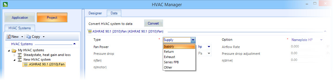
- Type – Displays the
fan type for each fan. Fan types cam be of the type Exhaust, Supply, Return,
Series FPB, or Other, and are defined in HVAC Manager.
- Power – Displays
the nameplate power specification for each fan.
- Design supply
airflow rate — Displays the maximum design supply airflow rate to conditioned
spaces served by the fans in all the systems.
- Fan nameplate power
allowance — Displays the sum of the allowable power of all the fans. This is
used to calculate the total fan horsepower allowance for the building.
- Total allowed
nameplate horsepower — Displays the total allowed nameplate horsepower for the
building fans. This is calculated by multiplying the design supply airflow and
the fan nameplate power allowance.
|
| Brake Horsepower
|
Displays prescriptive results for the fans in the
project building when the brake horsepower compliance option is used (Section
6.5.3.1 Fan System Power Limitation). The results reported here provide
information about each fan which is then used to determine the fan power
limitation for the building. Fans are typically the largest energy consuming
components of HVAC systems. The fan power limitation regulates the amount of
power used for fans, improving efficiency, and is defined as the ratio of the
fan system power to the supply fan airflow rate at design conditions. To
comply, the total fan power used by the fans in the building must not exceed
the limits prescribed in the standard.
- Tag – Displays a
designator for each fan that is found on the fan nameplate.
- Description –
Displays the fan object name for each fan.
- Type – Displays the
fan type for each fan. Fan types cam be of the type Exhaust, Supply, Return,
Series FPB, or Other, and are defined in HVAC Manager.
- Airflow rate –
Displays the full load air volumetric flow rate going through each fan at a
standard temperature and pressure (dry air at 20 °C/68 °F).
- Pressure drop –
Displays the pressure drop across each fan.
- ηfan – Displays fan
efficiency for each fan. Fan efficiency (ηfan) is a number between 0
and 1 and is defined as the ratio of the power delivered to the fluid (air) to
the electrical input power.
- ηdrive – Displays
fan drive belt efficiency for each fan. Belt efficiency (ηbelt) is a
number between 0 and 1 and is derived from three maximum efficiency
(ηbelt,max) curves for belts (low, medium, and high) as a function
of maximum fan shaft torque. This set of efficiency curves is based on belt
drive loss data from AMCA Publication 203 (1990b), which is an aggregation of
data from over 400 tests.
- ηmotor – Displays
fan motor efficiency for each fan. Motor efficiency (ηmotor) is a
number between 0 and 1 and is the shaft power divided by the electrical power
consumed.
- Power – Displays
brake horsepower for each fan. Fan brake horsepower is the product of the
airflow rate and the pressure drop divided by the product of the fan rpm and
the fan, motor and belt efficiencies.
- Additional pressure
drop – Displays the pressure drop adjustment for each fan. Pressure drop
adjustments can be positive numbers (credits) or negative numbers (deductions)
and are listed in the Standard (Table 6.5.3.1.1B Fan Power Limitation Pressure
Drop Adjustment).
- Additional
allowance – Displays additional allowances for each fan. Additional allowances
are derived from the pressure drop adjustment and the airflow rate.
- Design supply
airflow rate — Displays the maximum design supply airflow rate to conditioned
spaces served by the fans in all the systems.
- Fan brake power
allowance — Displays the sum of the allowable power of all the fans. This is
used to calculate the total fan horsepower allowance for the building.
- Base allowance —
Displays the overall base allowance for all brake horsepower fans. Base
allowance is the product of the brake horsepower allowance and the airflow
rate.
- Additional brake
allowance — Displays the overall brake allowance for all brake horsepower fans
which is the sum of all the individual additional allowances.
- Total allowed brake
power — Displays the total sum of all the brake horsepower the building fans
consume. This is used to calculate the fan power allowance and adjusted power
allowance for the building.
|